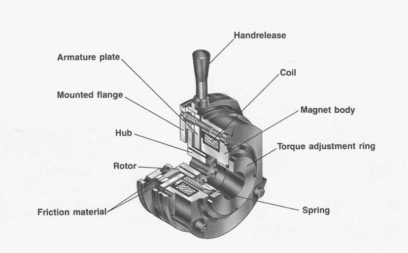
Friction material is bonded to the rotor; the rotor is splined to the hub which is keyed to the shaft. When no power is present, the rotor, hub and shaft are clamped between the mounting flange and the armature. During dynamic stops, heat is generated between the friction lining and mounting flange on one side of the rotor, and between the friction lining and armature on the other side of the rotor. The mounting flange and the armature are both effective heat sinks that can dissipate relatively large amounts of energy.
When DC power is applied to the coil, magnetic force pulls the armature into the magnet and compresses the springs. This releases the rotor, hub, and shaft, which are then free to rotate.
The torque of the brake, and therefore the stopping time of the machine on which the brake is applied, can be adjusted by turning the torque adjustment ring. Turning the ring clockwise increases the spring force which increases the torque. Turning the ring counterclockwise decreases the spring force which decreases the torque.